 Cause & Effect Matrix in Safety PLC / DCS — Explained Simply
In process plants, safety actions must happen automatically and correctly during abnormal conditions.
That’s where the Cause & Effect (C&E) Matrix becomes critical 
 What is a Cause & Effect Matrix?
 A document that defines:
 CAUSE → Abnormal condition detected
EFFECT → Action the system must perform
 It is the logic blueprint for SIS / DCS implementation
 Simple example
 Cause: High-High Pressure
Effects:
 Trip pump
Close shutdown valve
Generate alarm
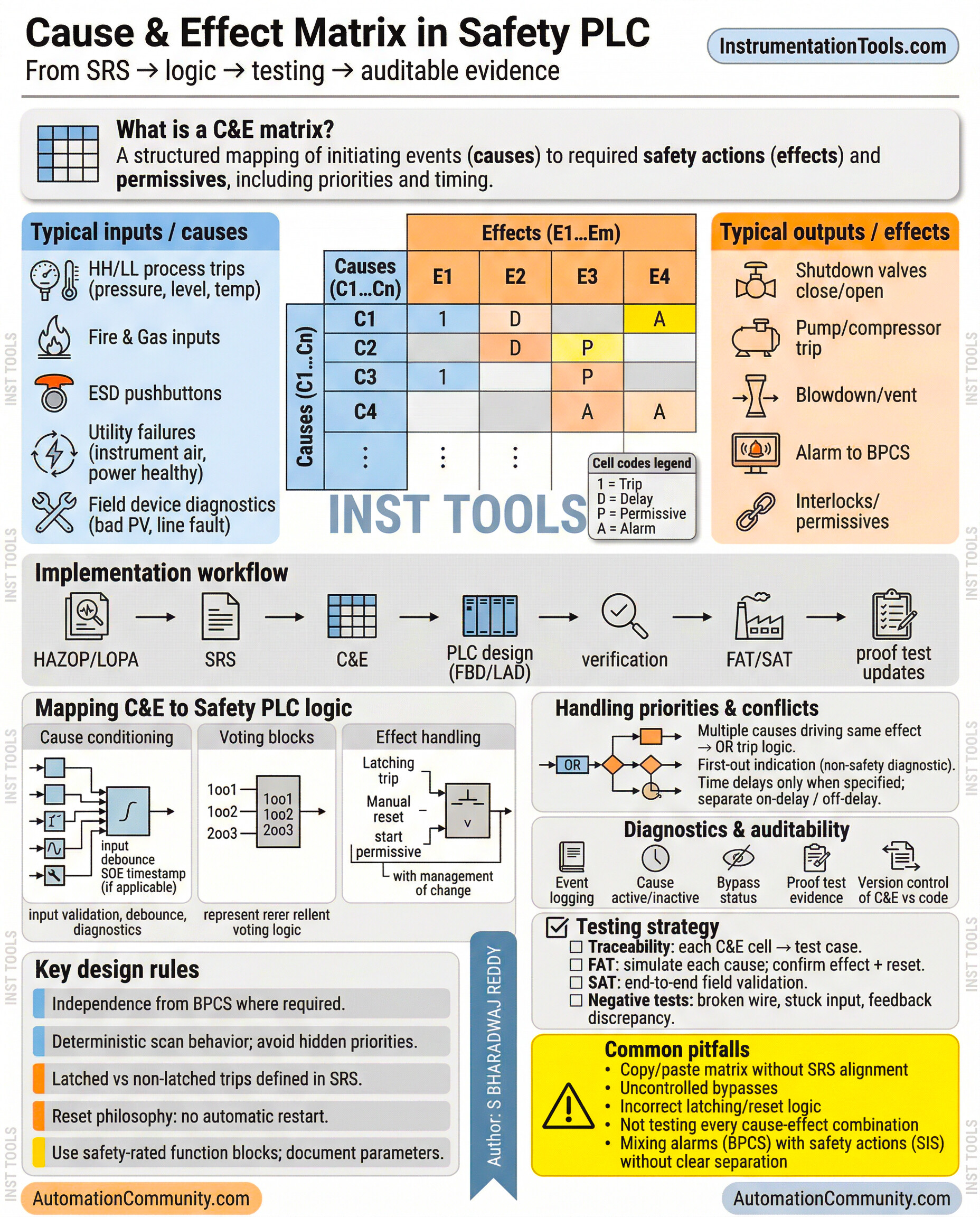
 Where C&E matrix is used
 Oil & Gas plants
 Chemical plants
 Power plants
Burner Management Systems (BMS)
Safety Instrumented Systems (SIS)
 How it is implemented in PLC / DCS
Inputs from field devices:
 Pressure transmitters
Temperature switches
Gas detectors

PLC / Safety PLC executes logic
Outputs activated:
 ESD valves
Pump trips
Alarms
Shutdown actions
 Typical implementation methods
Ladder Logic
Function Block Diagram (FBD)
Cause & Effect logic tables
Sequential shutdown logic
 Important engineering practices
 Logic must match approved C&E matrix
Proper bypass/interlock handling required
Sequence of Events (SOE) recording important
Testing & validation mandatory
 Key takeaway
C&E matrix converts process hazards into automatic protection actions
 Simple understanding
Cause detected → System reacts automatically
That’s the core of every safety shutdown system.
#SIS dcs #CauseAndEffect #ProcessSafety #FunctionalSafety #Instrumentation Automation #ControlSystems #Engineering #SafetyPLC