DIP Switch Input and 7-segment Display Output
Control Purpose:
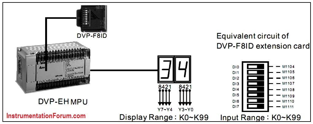
Setting the set value of counter C0 in the range of K0~K99 by DVP-F8ID extension card and displaying the PV (K0~K99) by 7-segment decoding display.
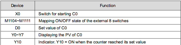
Devices:
Program Description:
-
When PLC runs, ON/OFF state of the external 8 DIP switches will be mapped to PLC internal auxiliary relay M1104~M1111 by DVP-F8ID extension card. 8 bits switch can perform 2 digit number input by instructions.
-
When the program is executed, M1000 = ON, and the set value of counter in DVP-F8ID extension card will be stored in D0.
-
When the counter is OFF, X0 = OFF, and the 2 digit number display will show the set value of C0 because of the execution of BCD instruction.
-
When the counter is ON, X0 = ON. C0 will start counting and BCD instruction will be executed. The 2 digit number display will show the PV of C0.
-
If the 2 digit number display shows “34” from left to right, it means the state of DI7~DI0 on DVP-F8ID extension card is “0011 0100.”
-
When C0 reaches its set value D0, the NO contact C0 will be activated and Y10 will be ON.